

It’s been a while, but we’re back!
I designed a builder’s logo when I was building short track speed skate boots. The logo was a triangular “VJ” – my initials. So, it seemed obvious to just add another “J” to indicate both our first name initials. You see – neither of us ever watched Oprah so we never thought twice about it. Now it’s simply a matter of principle – we had it first! This emblem is about 3.25 inch diameter from 1/8 inch thick aluminum bar with letters milled about 1/32″ deep. Surprisingly, the hardest thing to source was just a bit of black dye powder. Forty pounds of the stuff is not that hard to find – but 3 grams? Ended up grinding up three pencil leads to colour the two part epoxy.
DYNO DAY:
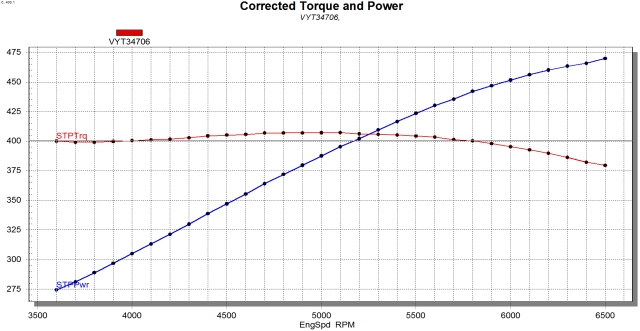
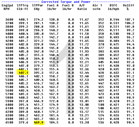
This entry is mainly about the completion of the engine build and the dyno run which was delayed for months for various good reasons. The engine completion was not near any critical path for build schedule, but there was always great anticipation to find out what the heart of the beast will actually do. We expected north of 400 HP and a reasonably flat torque curve and as you can see in the video those expectations were met and surpassed by a fair margin. As a road car with a mild 3.27 rear end and a T56 six speed this combination will have to be handled with some respect.
Now for the NOISE (speakers up please):
Many thanks for Venice Perno, owner of Performance Cellar in Stoney Creek, Ontario for his selection and build of components that yielded a fairly economical package that will keep us more than entertained.
An unheated garage does not lend itself to any assembly progress on the build. Fortunately, there is a heated shop set up with very basic hand tools and a new mini mill described in the previous post. So, with time available, lots of hours were spent making big bits of aluminum and steel into smaller, more useful bits. None of these little projects were, strictly speaking, necessary as there are many commercial options that would would have yielded the desired results – but where’s the fun in that?
Pedal Assembly:
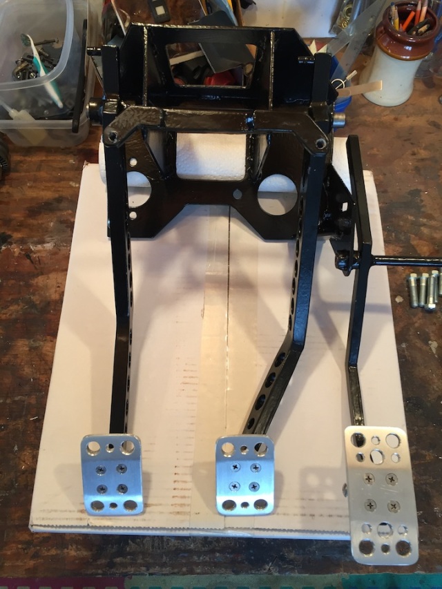
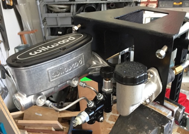
In a previous post we outlined the basic design of the pedal fabrication and the assembly/weld steps. The geometry is based on Wilwood pedal assemblies since those are the primary brake and clutch actuation system components. Pedal location and spacing borrows a page from my Subaru WRX STI which suits both our driving needs very well.

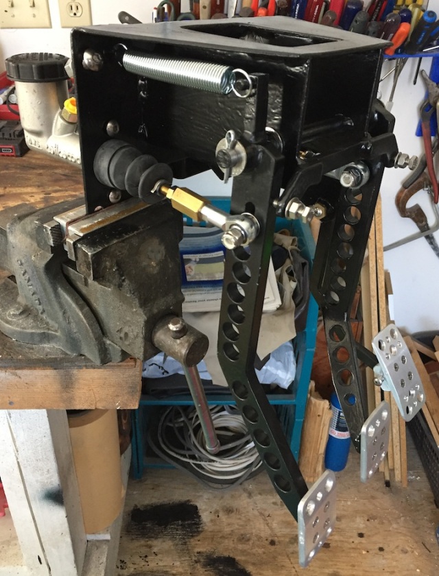

There is adjustability built in for pedal lever ratios and pedal distance to the seat so that the final driving position is not compromised. The pedals themselves are an easy execution starring with .25″ by 2.0″ aluminum bar, milling a few angle faces. and then drilling a few holes.
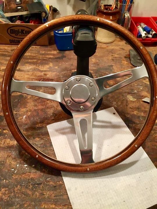
Horn Assembly:
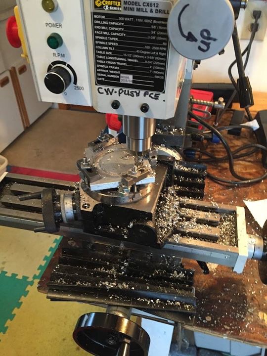
This design can also be found on a previous post. The three normally open pushbutton switches which ground the horn relay coil are catalog items sourced on line from DigiKey. The aluminum button and outer ring were machined from solid blocks using a rotary table on the mini mill. This is not a machine shop quality tool so precision takes a big dose of patience and obsessive compulsive disorder.
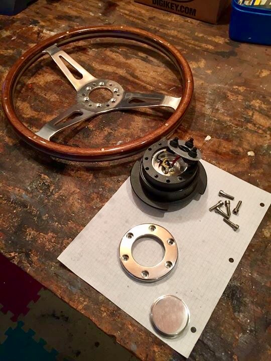
Initially, the thought of polishing aluminum was a bit scary. Progressive wet or dry sanding with 220, 400, 800, and 2000 paper and then a quick polish with a liquid abrasive easily sourced at just about any auto parts supply store. The steering wheel is the kit wheel from Factory Five mated to an NRG quick release so that getting in and out of the car is a bit more graceful. This kit steering column is replaced with an Ididit unit to make self cancelling turn signals and an emergency flasher switches easily available.
Shift lever, knob and reverse lockout switch:
The shift lever will be straight and short since the engine location is 4 5/8″ forward of the stock kit location and a T56 Tremec tranny is being used with the shift lever in the centre of the three available positions. The shift pattern of the T56 places reverse in the upper right quadrant beside 5th gear. This is not the best spot in the world for fast 4-5 upshifts or 6-5 downshifts so Tremec’s solution is to install an electric solenoid lockout mechanism that requires the lockout coil to be energized to easily engage reverse. There are as many solutions on how to energize this coil circuit as there are folks on build forums.
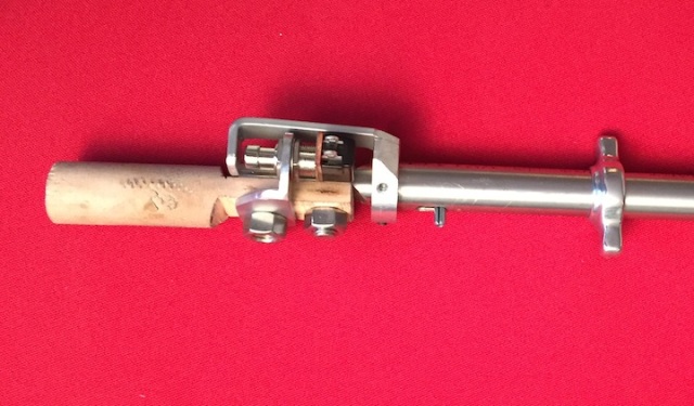
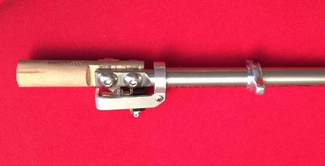
We installed a normally open switch which an be activated by lifting a small dog-bone lever on the outer sleeve of the shift lever shaft. Once in reverse, the circuit is kept energized by the reverse switch in the tranny itself. The two switch combination will also engage the back-up lights and the backup camera. All the lower nastiness will be covered by a leather shift lever boot.
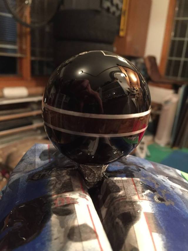
While it’s probably possible to get a plain black shift knob with the correct shift sequence embossed we lost the will to live after some initial net searches. We acquired a “Hurst” embossed knob for a Corvette and replaced the lettering with an aluminum/burled walnut/aluminum sandwich using a hacksaw.
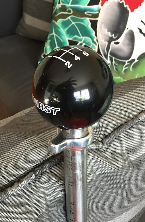
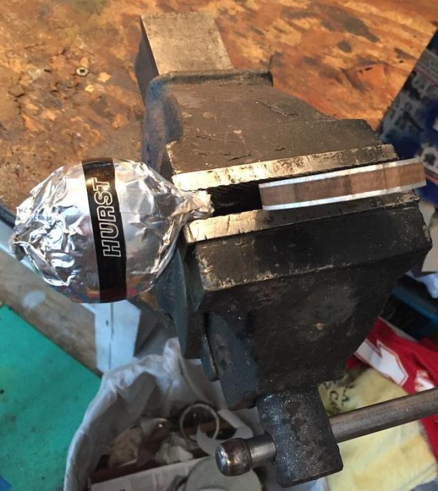
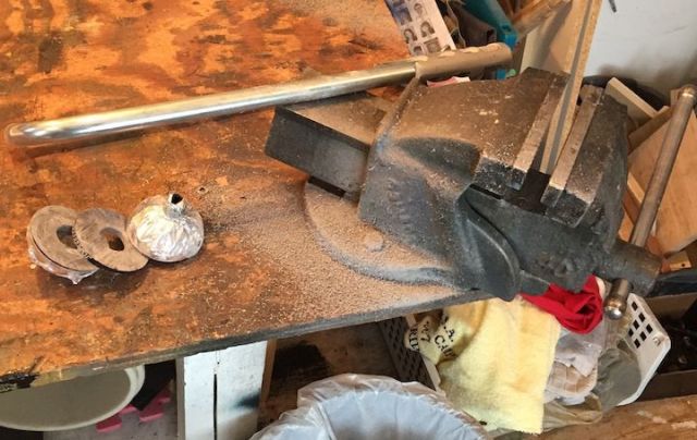
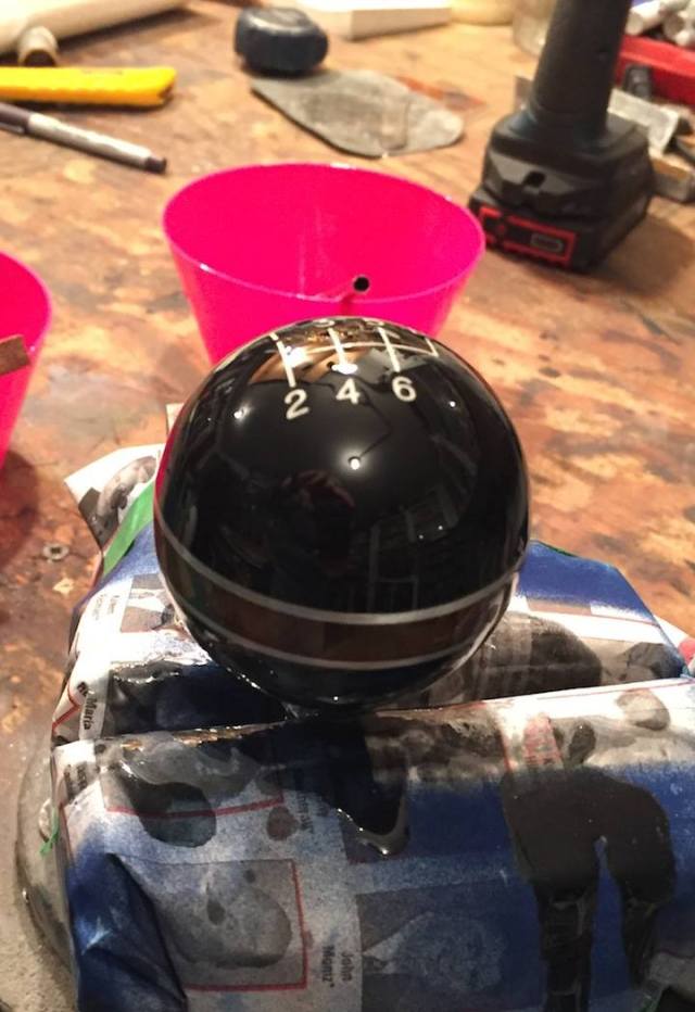
Sandpaper, epoxy, a file, more sandpaper – and a two part flow epoxy used to cover the bar at any of many local watering holes. The lever still needs to be cut to length once we get a chance to test fit in the cockpit.
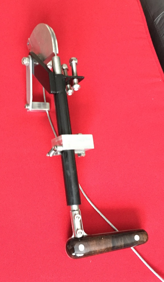
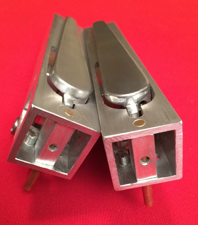
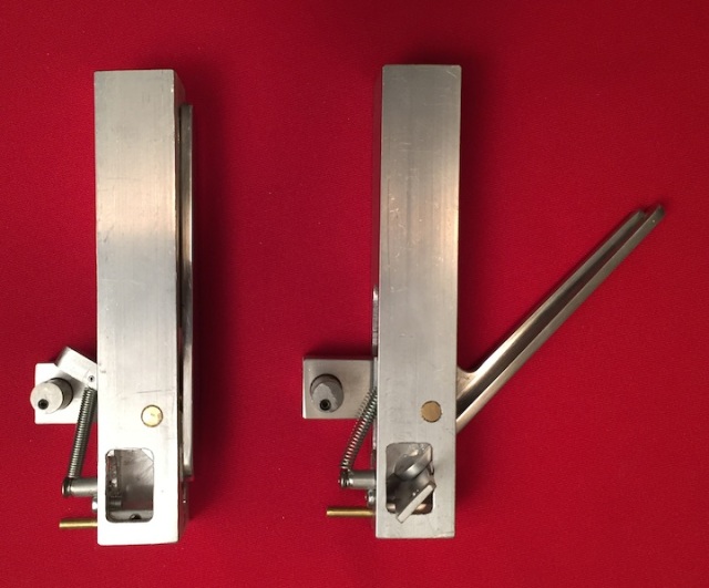
Parking brake handle:
As described in an earlier post the original kit location of the parking brake lever did not suit our liking. The new pull assembly has a 4 to 1 lever ratio with about 4 inches if handle pull for one inch of parking cable pull.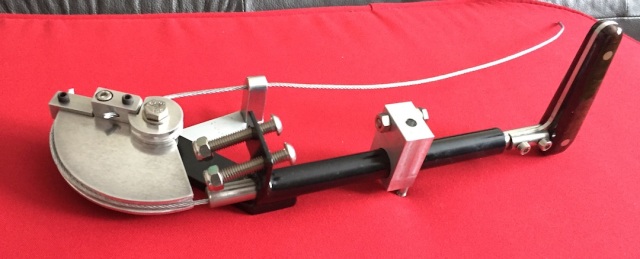
The brake will be located top and left of the narrowed tranny tunnel, with the actuation cable running in the upper left hand corner of the tunnel interior. The pull lever ratchets to engage and lock, and twists about 70 degrees to disengage. Obviously, the handle had to be burled walnut.
Door handles:
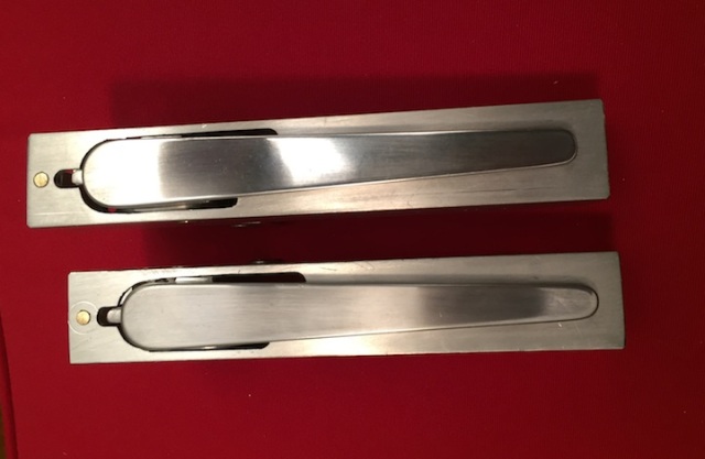
The standard kit does not come with external door handles or door locks. Again, designing and making is way more fun than just buying. The kit door latches are cable operated with about 1/2 inch cable pull required to unlatch.
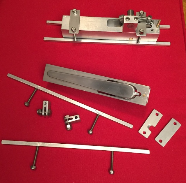
The lever design has cable slack to allow the lever to easily rotate the first 30 degrees out the door and the final 15 degrees rotation pulls the cable to unlatch the door. The actuation cable is a simple bicycle brake cable available at any decent bike shop. Those cable assemblies are very flexible and allow some tight radius cable turns so interior door routing around door window hardware and mechanisms is possible.
The assemblies will attach to some bars bonded to the door under skin. Locking is accomplished with a rotary lug that slips under the handle in the locked position, rendering it inoperative.
 Standard key operated door lock cylinders are rotary so connecting the two will be some simple bar/lever link. We haven’t sourced the key lock cylinders yet, but I’m sure our friends at Performance Improvements will be more than happy to help when the time comes.

You’re having way too much fun with this. Beautiful work! I’m looking forward to the next visit.The Best to You,Roger
From: The Factory Five Type-65 To: scaledesign@rogers.com Sent: Friday, February 24, 2017 3:56 PM Subject: [New post] Massive update, Interior bits, and NOISE!! #yiv4715773503 a:hover {color:red;}#yiv4715773503 a {text-decoration:none;color:#0088cc;}#yiv4715773503 a.yiv4715773503primaryactionlink:link, #yiv4715773503 a.yiv4715773503primaryactionlink:visited {background-color:#2585B2;color:#fff;}#yiv4715773503 a.yiv4715773503primaryactionlink:hover, #yiv4715773503 a.yiv4715773503primaryactionlink:active {background-color:#11729E;color:#fff;}#yiv4715773503 WordPress.com | vjjfactoryfive posted: “It’s been a while, but we’re back!I designed a builder’s logo when I was building short track speed skate boots. The logo was a triangular “VJ” – my initials. So, it seemed obvious to just add another “J” to indicate both our first name initials. You s” | |
LikeLiked by 1 person
Vyt, looks like retirement is suiting you quite nicely. I’m sure you’re asking how you had time to go into Westinghouse/Siemens before. Wow, great stuff and yes why buy it when making it looks like much more fun and rewarding. I love the one of a kind custom handles and knobs. Keep up the good work guys. I’m sure Jonas is thankful everyday he has a mind like yours to figure out all the solutions to every problem or next step along the way. Keep me up to date as things progress.
p.s. Is the reservoir on the clutch pedal linkage for a hydraulic clutch?
LikeLiked by 1 person
My father can figure out a LOT of things,but responding to this post could be an issue for him :-). Im an extremely lucky guy having a father with these kinds of skills, absolutely. To answer your question, yes, that is a reservoir for a hydraulic clutch.
LikeLike