

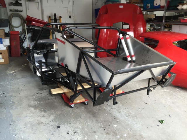
Once the car chassis and assorted parts were moved into the garage and organized we took an inventory of all of the parts and removed the fiberglass shell and inner aluminum panels to start work on the suspension and frame modifications.
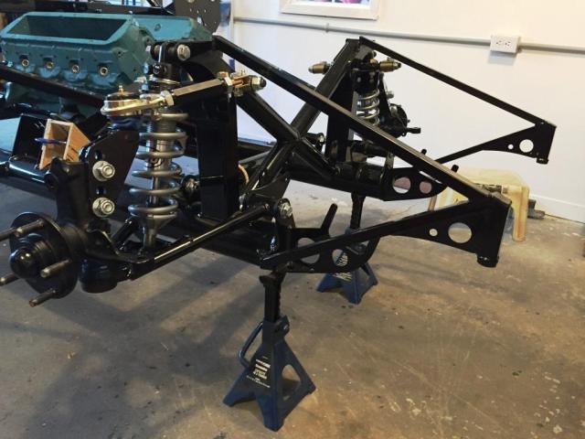
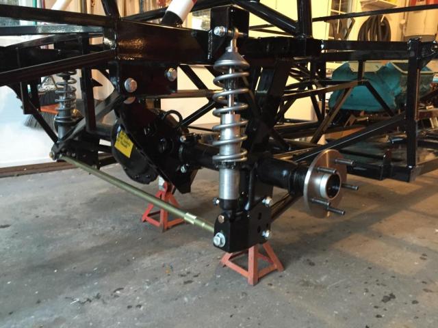
The suspension assembly was a very straight forward process using our new QA1 coil-overs supplied by Chrome Paint’n’Rods out of Montreal QC
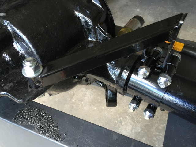
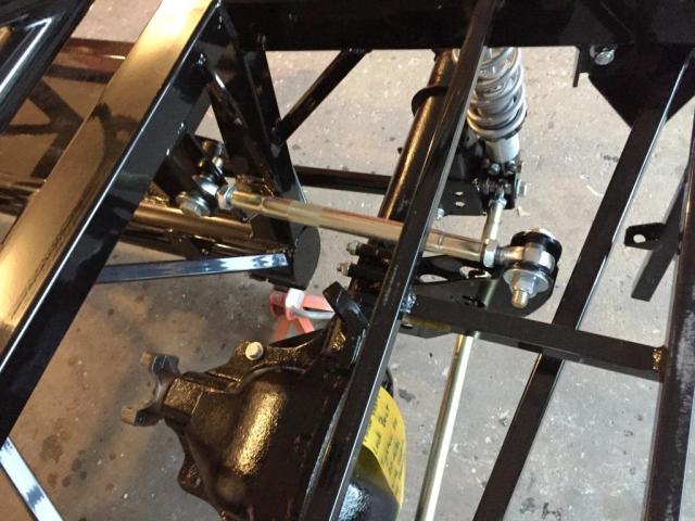
The 8.8 inch Ford rear end required a single hole drilled to align and fasten the 3 link suspension kit supplied by Factory Five – everything else went together like a giant Meccano set.
As we found on our two visits to FFR the interior of the 65 coupe gets a little cramped if you are well above the “average” male North American frame size of about 5′-10″ and under 190lbs with feet a size 10 or smaller. This probably stems from the cars development as a close cousin to the Roadster.
For someone with a 6′- 4″ frame of generous proportions and size 14 feet something needed to be done.
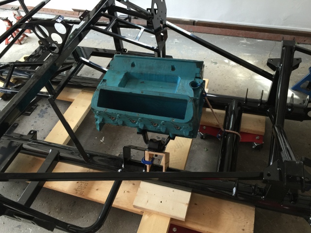
Close examination of the engine placement showed that it restricted foot box width and length to make room for the exhaust headers. etc. There appeared to be at least 6 inches of free space in front of the engine before any serious interferences would occur. At first blush it may appear that a significant engine forward move may negatively affect the car’s weight distribution. A few calculations revealed that the weight distribution approaches a more favorable 50/50 with a rather large engine move forward.
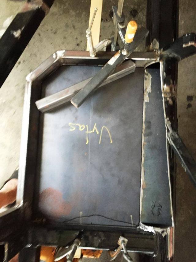
This image shows the cut of the rear of the original engine mount.
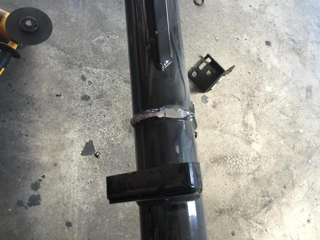
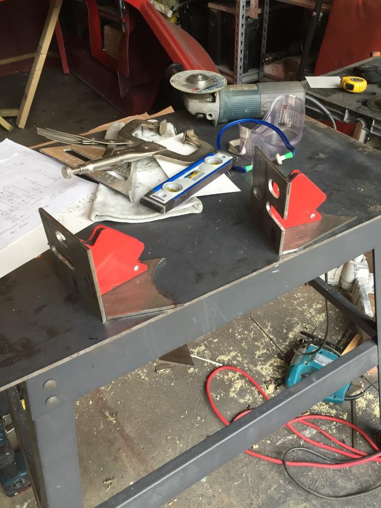
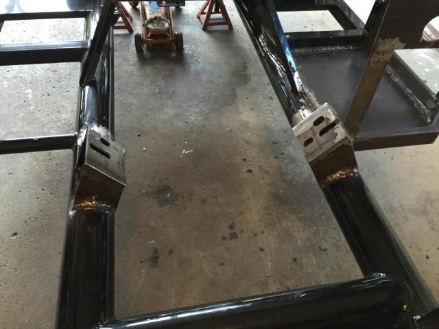
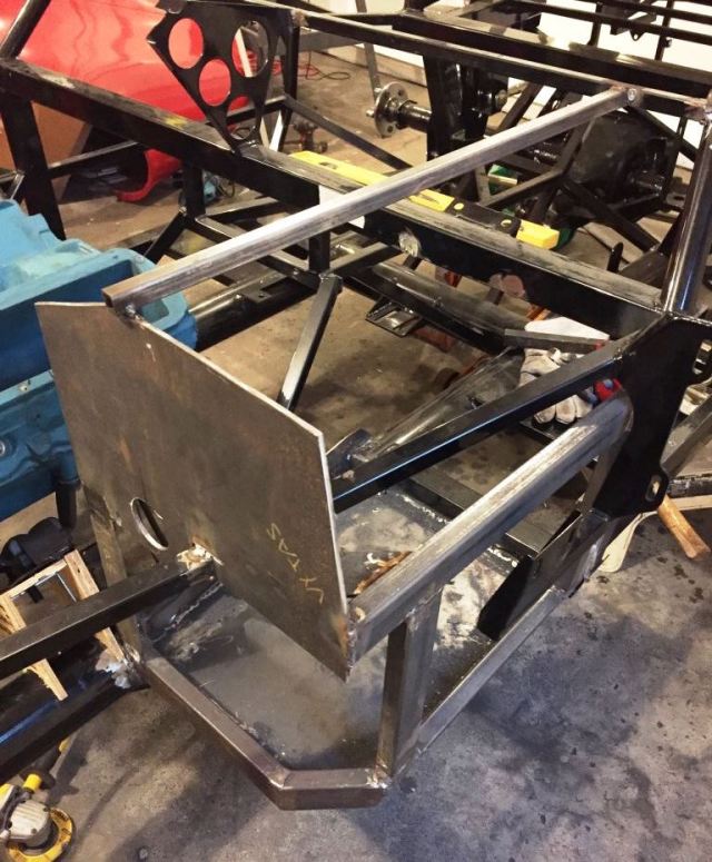
Using the original removed mounts as templates, new engine mounts are fabricated and welded onto the chassis.
Here you can see where the old mounts were cut and ground down and the new mounts are welded in place 4 3/8″ ahead of the original location.
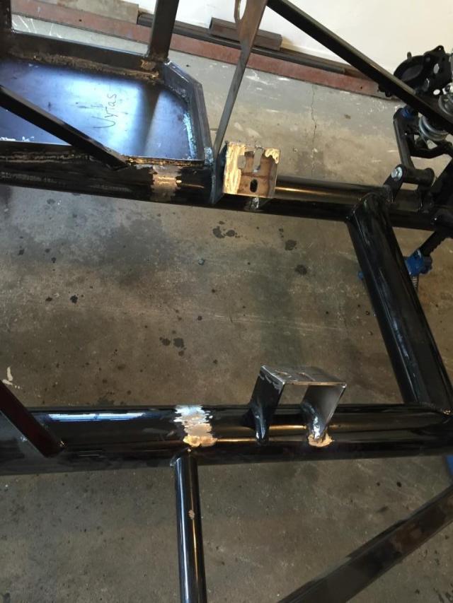
This large an engine move makes the engine mount mods fairly easy since the original forward support webs of the mounts can be retained. This makes precise mount alignment straightforward.
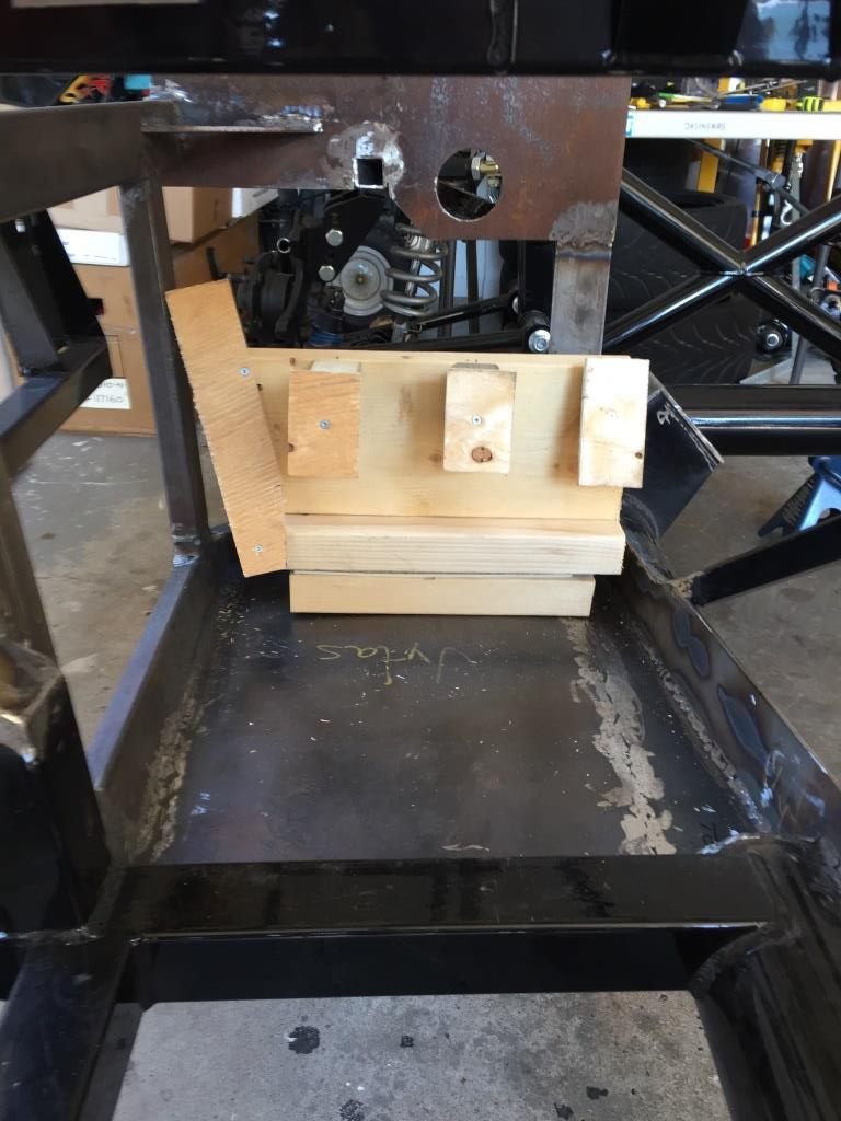
After fitting a dummy foam engine block and looking at the chassis engine mount design, a 4 3/8″ move (one axial cylinder pitch) forward yields a lot of benefits. The foot box can be lengthened by 3 inches and widened by 1 1/2 inches by relieving part of the top half of the main 4 inch chassis tube in the foot box area. A vertical partition web partially restores the section modulus of the frame tube.
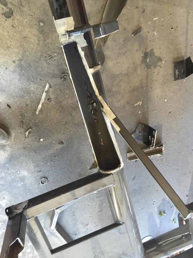

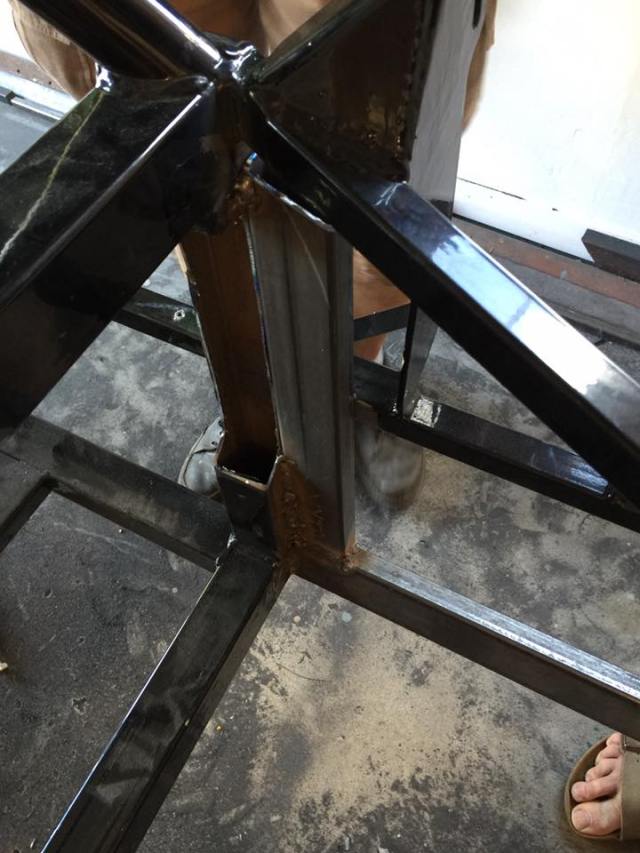
The new foot box has a full 1/8 inch think floor and added structure on the outside, on the end, and overtop add to the stiffness of the area. This heavy outside structure also allows the partial removal of the frame strut that goes to the front suspension structure. This provides the room necessary for an electric power steering unit to be installed at the top of the box – out of the way of external heat sources. The outside lower foot box corner is cut away to allow the exhaust pipe to exit the body in its intended location.
Reference point to point measurements of the chassis structure showed no distortion after the rather extensive amount of welding.
The steering shaft position and angle remain stock. We did move the dash bar position 1 1/2 inch forward so the steering wheel could be pushed forward if needed.
The dash to firewall volume needed for wipers, AC/heater unit, instruments and wiring can easily be doubled with the engine move. More on this as the build progresses. The transmission goes forward as well, so now the typical center back placement of the T56 shifter will end up at just about perfect reach form the driver’s seat. A longer driveshaft is a good thing as well since this reduces the drive angles a bit.
We designed custom foot pedals with spacing and placement almost identical to my Subaru STI. It’s easy to build in side to side and fore and aft adjustability so that the right pedal feel can be dialed in. More on this later.
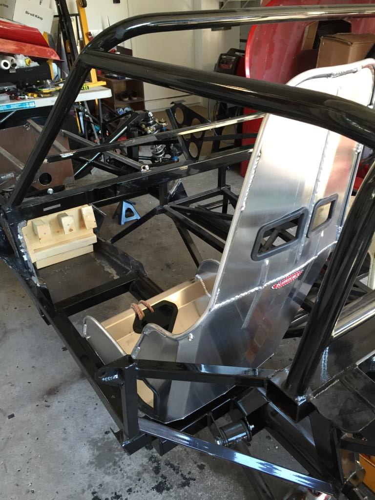
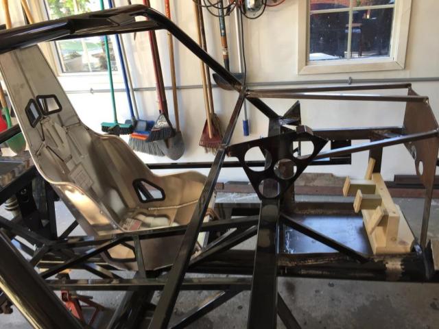
Next major step is seat placement and adjustability. We are looking at an 18 inch wide Kirkey as a starting point. Unfortunately, floor mods look to be out of the question given the required rearmost position of the seat and the location of the rear suspension trailing arm pivot points. We are not that tall seat to head so headroom should not be a problem, but wearing a helmet is probably not going to work.

I’m loving it. BTW, can you use hole plug cutters for the instrument panel, etc.? I’ve got a set I got for the aircraft build. I could bring them this coming week.
Regards, Roger
LikeLike
I can’t speak for my dad- but I would say sold!
LikeLike